Tuesday, April 18, 2023

Home Theater Fan Repair


These days it would seem as if every product were manufactured with an engineered lifespan. I find this particularly true with cheaper electronics. Parts and components of a unit typically fail at what seems suspiciously close to mere weeks after a warrantee period has ended. For some, this equates to the slow sad procession of obsolete electronics to the curb on trash night. To others like me, it lends an opportunity to open a unit up to see if something could be repaired or at least harvested for parts.

Case in point, my father gave me an old surround sound decoder he no longer wanted. I had purchased him a sound bar which better suits his needs and he simply wanted to discard the old decoder. I had asked him if it worked, and he said that it did but that it made a “funny noise”. Not deterred, I took it home and opened it up.

               Once the cover was off, nothing seemed out of the ordinary. Typically, the first thing I look for is any signs of stress or wear on the components. None of the capacitors looked swollen and there were no observable burn marks or loose solder joints. So, at first glance everything seemed ok.

               The next thing I did was hook the speakers up, apply power to the DUT (device under test) and then listen for or smell if anything seemed out of place. No sparks, or smoke erupted when power was applied. Furthermore, nothing seemed to burn or smell different. The speakers had a very slight hiss to them when the volume was turned up, so nothing with them sounded like a “funny noise”.


There was, however, a guttural whirling that emanated from the DUT. On closer inspection it appeared that the fan was struggling to spin. “Ahh this must be the problem!”, I thought. That seemed like a simple enough fix. Maybe even a quick blast of air could remedy things.

               I popped the fan out of the DUT and gave it a good blast of air. I noted that as per the label the fan ran on 12 volts, so I decided to hook it up to a power supply to ensure that the fan was still in working order. I dialed up the voltage on the power supply and the fan snapped to life with vigor. It ran a little loud, but it moved the air just fine. I was confident that the issue had been resolved and replaced the fan in the DUT.


Upon testing, the fan performed in the same manner I had originally observed. It struggled to spin. This led me to believe that somehow the board was not providing the voltage necessary to turn the fan.

               I disconnected the fan and read the voltage with a multimeter at the connection point. It was a little over 8 volts. “Well, that is not 12 volts so that HAS to be the problem.”, I thought to myself.

               At this point I was a little over my head. Somewhere, I imagined there had to be bad components buried in the complex circuitry of the DUT. I searched with no success to find a schematic. I attempted to look at the traces on the board to get some sense of where to look next. Ultimately, I just started to randomly probe around looking for 12 volts on the board.

               When none of this worked, I decided to enlist the help of fellow club member Chris Prioli, AD2CS. He informed me that he would be happy to take some time and look at my problem.

               More often than not, there is always something going on at the clubhouse every Saturday. Whether it is a Tech Saturday presentation, the satellite station flexing its muscles on the newest satellite deployed or restoring the clubhouse to better than former glory. The activity there is both welcoming and productive. This was the perfect place to meet up with Chris, and to get some use out of the clubhouse’s test bench.

               I met up with Chris early on Saturday morning and after a few moments of discussing Chris’ latest project we moved to the test bench to diagnose my issue. I explained the problem that the DUT was experiencing to him. He then did a quick search for a service manual to no avail.  We also removed the board in question and did a visual examination, nothing seemed out of place.

Next, we hooked the DUT up to the test benches’ isolated AC power supply. This was an interesting piece of test equipment that isolates any circuit powered by it from AC mains. It also had the ability to adjust the voltage so that a user can slowly increase the voltage up to the recommended value. The DUT powered up normally and when turned on via the front panel switch, the fan began to intermittently spin.

               Up to this point the steps taken were nearly identical to what I had performed in my earlier analysis. Chris, however, took a different approach when he checked the voltage being delivered to the fan. Instead of using a multimeter he opted to use the oscilloscope instead. I asked about this and he informed me that the “scope” could give us much more information about the voltage than merely its value. For instance, it can tell us if it is flat or alternating in any form over time. For the DUT it appeared that the voltage was a flat DC value a little more than 8 volts. This led us to believe that the voltage being delivered was probably not the issue since it was constant, with little to no ripple in it.

               Chris had me remove the fan again, and he visually inspected it.  “Look here.”, he said to me while spinning the fan blades with his finger. He continued, “The fan does not spin smoothly, there is some resistance”, while flipping the power switch of his custom battery eliminator. This is a piece of test equipment that Chris had built of his own design. It allows a user to flip through a series of DC test voltages that are common battery voltages. We started low at 1.5 volts and gradually increased. The fan started to intermittently turn at around 8 volts and finally started spinning consistently around 12 volts.

Then it occurred to me that DC fans should ideally start spinning with low voltage and gradually get faster, NOT run intermittently. It seems like an obvious enough thought, but it had indeed eluded me, with my limited experience in troubleshooting. So, my original impression that the fan was the issue was correct and Chris agreed.

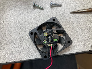
Rather than order a new fan, Chris wanted to see if we could restore the operation of the fan under test. He peeled off the label on the back of the fan to expose the electronics and bearing. He then used component cleaner and compressed air to dissolve and blow out any dirt in the moving parts. Finally, we hooked the fan up to a voltage source to get it spinning and we applied oil to the bearing. Now the fan spun smoothly as soon as voltage was applied. We reinstalled the fan and the DUT now had no issues.

There were a couple of different ways that I could have addressed the problem. I could have scraped the unit for parts, or I could have merely ordered a new fan, waited for its arrival and installed it. Either would have worked out for me, but I feel that it would have wasted the opportunity to learn and collaborate with fellow enthusiasts. After all, isn’t that what being in a club is all about?


Sunday, January 15, 2023

The Six Meter Moxon

 For some time now I have been punishing my antenna tuner and radio by attempting to tune a ten-meter hamstick dipole to six meters. At times, I could just barely keep my radio transmitting long enough to squeeze out a few FT8 contacts. There had to be a better way to get on six meters. Sure, I could just buy a few more hamsticks for that band but I'd like to save that money for the purchase of a GOOD multi-band vertical, if at all possible, Plus I have a bunch of wire and building materials just laying around from my years of hoarding such things. So, I thought maybe I could try and build an antenna for six meters.

This is nothing new for me. In the past I have attempted to build a three element Yagi out of discarded tape measures, and even simpler, a dipole I made out of galvanized conduit. I was never able to get the Yagi to work properly and the PVC support for the tape measures sagged comically. I did however get the dipole to work somewhat properly, and I think I even recall making a contact to someone in Delaware., but the whole thing was heavy and unwieldy. I simply lacked the equipment, the knowledge, and the patience to make a decent antenna of moderate size.

Now a days we have great tools like the Nano VNA and PSK Reporter. For me this makes building and testing antennas so much easier. In the past I merely hooked an antenna up to my little MFJ-259 to see that it wouldn't burn out my finals if I transmitted. I really had no way of seeing any other attributes or performance statistics. At least none that I could visualize.

So, I think this time around I am better prepared to come up with a solution to getting onto the Magic Band.

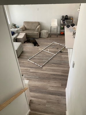
I had both heard, and read about an antenna called a Moxon, that offered decent front to back ratios, was compact, and depending on design very light weight. There are many webpages and videos that detail how to build these antennas but, in the end, I settled on this site. Not for any particular reason other than I had most of the materials needed for this design. I roughly used the dimensions outlined and just trimmed things until I liked what I saw. Below is the antenna in mid-construction. I merely used electrical tape to secure the wires to the PVC, knowing this was just a test and not anything permanent.


Once I got the antenna together and up on a mast it was time to tune it. The antenna was about twelve feet off of the ground and I took some readings with the NanoVNA.


The first reading came up a bit low. Around 47.5Mhz. Much too low for the six-meter band.


After a few snips with the wire cutters, I was happy where the antenna was roughly tuned.  Below 2:1 SWR for about half the six-meter band.

Next it was time to map out the antenna pattern. To do this I set up WSJT-X software to call CQ on FT8 on the six-meter band. I would lower my wattage to its lowest setting and then just walk around the antenna in a circle thirty feet away from it with a signal strength meter on each transmission. So, standing directly in front of the antenna at thirty feet distance I adjusted the field strength meter to 100% during transmission.

Walking 90 degrees on either side of that point read 100%.


The 180 degrees behind the antenna produced 30%. I felt that this was a very good front to back ratio and allowed decent directivity.


Armed with this information I pointed the antenna West and turned up the wattage to 95 watts and started calling CQ. When I visited PSK Reporter to look at a reception report I was amazed at how far my signal got. I really wasn't expecting to see Texas light up. There must have been a band opening or something to the like.


So, I felt this little experiment was a success. Once I get more time, I would like to build a lighter version of this and get it up on my roof with a decent rotor. But for now, I will take the success that I got.


Saturday, January 14, 2023

The Amazing Melting Antenna

 These days you are much more likely to see solar panels on the roof of a house than you are to see a television antenna peaking above its highest point. This of course is due to technological progress and the dominance of cable TV. 


At some point the temptation of a glut of channels seemed to be worth the ever-increasing cost of having a cable come into your home, and force feed you more reality shows and highly opinionized news then any one person could conceivably imagine. At the price a person pays, the compulsion to lock your eyes open and stare at the vast emptiness of quality programming seems to be almost natural if not necessary. 

Noticing this gaping monthly hole in our wallet combined with the bad taste in our mouths from what was actually being offered to us the watch, the wife and I decided to cut the cable and rely solely on streaming services, and OTA (Over the Air) television.

To accomplish the reception of over the air television (yes, it is still being offered), I put up a small antenna pointed at a particularly thick congregation of television antennas seven-teen miles northwest of my location.


This antenna was once available on Amazon and does provide decent service. It happily hung out on my roof for a few years with a variety of other antennas, sensors, and plumbing.


Recently, however I had noticed a distinct drop in signal strength and quality of picture. Something was wrong up there, and I did not know what. Perhaps some of the high winds we get moved the antenna out of alignment. I had to go up and see.

What used to be an easy climb up onto my roof has since become somewhat of a task the older I get. Nonetheless I did hobble up to see what was going on. The first thing I noticed was the antenna was absolutely COVERED in bird shit. Is bird shit conductive? Was it shorting something out? I did not know. So, whatever the reason I had to take the antenna down and clean it up.

Below you can see the antenna after it has been cleaned up a bit. It does still appear a bit rough around the various feed points. In my attempt to clean those up, the plastic holding them secure fell apart in my hand. I suppose the years of it baking in the sun and bathing in bird shit had just deteriorated them. 


Luckily, I have a 3D printer and a mind to use it.  I was able to design and print a reasonable facsimile that worked rather well.


This time I mounted everything in the attic to keep the birds away from the antenna. I pointed things in the right direction, and everything was good. The signals were strong, and the picture was solid. I had all of this completed before the summer heat got too hot to work in the attic.

After about a week I started to notice that channel 2 was not coming in at all. This didn't make sense to me since the signal was nice and strong when I hung the antenna. I popped up into the attic to take a look and this is what I saw. The elements responsible for VHF-Lo band reception (Channel 2) were bent over and sagging as if they were sad. On further inspection when I took the antenna apart, I found out that my printed PLA parts had gone soft and melted a bit.


How was this even possible? The attic should never get that hot. Well apparently, it did because I had found that my attic fan had stopped working. So, I took the antenna apart and put it to the side while I fixed the attic fan.

In the end however I hooked my discone antenna up as a stop gap until I repaired the directional antenna again. Come to find out that the discone antenna works WAY better than the direction one I fixed. So, I just left it in place and have not had issues with it since.


Another lesson learned; I suppose.


Sunday, July 24, 2022

The Inverted V experience

 
I know its been a while since my last post and life often gets in the way but my antenna building efforts have been rekindled and the next few posts will probably be about those efforts. 

So when we last left off, I was attempting to use a 1:1 balun on a receiving antenna to hear signals from Jupiter. Due to poor design, poor construction, and a crabby neighbor, I ended up dismantling everything.

Since then, I've found out that my crabby neighbor, whom I had assumed was just a grade A ass was really sufferings from a mental breakdown.  Its weird how being an ass and having a mental issue look so closely alike. I suppose I should try to approach things with more empathy. Suffice to say, I don't think I will have issues with him hindering my antenna building efforts in the future and if I do I will slap a healthy dose of PRB-1 on him.

So, every Tuesday night a bunch of operators from the local radio club have a net on 10m. This is basically an organized forum to communicate at a frequency of around 28.465Mhz. Ever since I joined the club I had wanted to participate in this net. I have been a licensed radio operator for more than 20 years but I rarely if ever transmitted on any band other than VHF/UHF. So I figured this would be a good opportunity to get my feet wet. The net is all local, so power and the antenna should not be too critical. The participants are mostly club members so they can guide me if I make mistakes, and the frequency is high enough so I can cobble together a simple antenna that is modest in size. Remember wavelength is inversely proportional to frequency.

For a design, I figured I would start with something I was familiar with and simple to construct. A dipole came to mind. I already had two 20ft telescoping poles from my Jupiter antenna to get wire off the ground, and I am already familiar with constructing dipoles. To keep the size and scope down I opted to construct an inverted V antenna. This way I only have to use one telescoping pole and the whole antenna takes up less real-estate. I am not particular about directivity and in fact prefer an omni-directional pattern so an inverted V seemed like the best option.

I had some old 10 gauge house wiring that I used for the elements. I simply used the formula Total Foot Length = 468/ Frequency in MHz. I, of course halved this to get each dipole leg length. Any errors I figure I could just trim off. I ended up with about 98 inches in the end after trimming, but I am getting ahead of myself.

Before the trimming I had decided to resurect the failed 1:1 balun I made. I basically threw out the instruction and just went with my gut feeling and what I could observe.

I basically just took two lengths of wire and twisted them together using a drill. I then coated this with shrink tubing and looped it around the toroid about 12 times. This should be effective as a 1:1 current balun or common mode choke.

Common Mode Choke under test

As you can see above I have the choke hooked up under test. One side is connected to a 50 ohm load and the other to me Nano VNA network analyzer.

Range of 3-30Mhz

I was pleasantly surprised to see a flat SWR (blue line) across the bands. This of course changed when I jammed everything in the box and the choke was connected to connectors and lugs.

The SWR (blue line) starts to creep upward as frequency increases, but it was something I could live with for now,

Once I got everything stuffed into the box, I hooked it up to the inverted V along with some rigging to hang the antenna by.


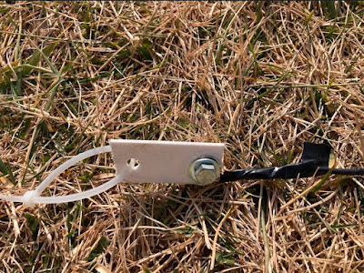
On the ends of the antenna I added these little plastic pieces to aid in flexibility when I attached the guy lines. Also I made sure that the ends of the dipole had wire loops on them so I could attached additional legs for other bands.

Sight selection was merely the side of my home that has no immediate obstructions.

The antenna only took about 15 minutes to erect and rig up, so for that I was thankful.

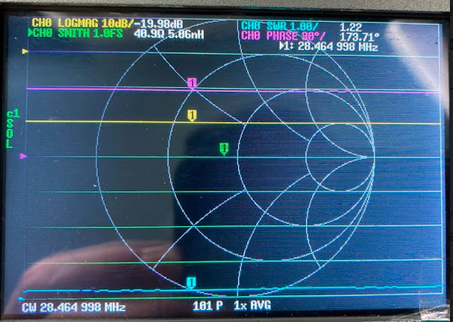
Inside on the Nano VNA the SWR looked nice for the 10m band. A pretty wide curve. BTW its the blue line we are looking at. :)


In the end the frequency of interest 28.456Mhz came in at an SWR of 1.22:1. This was good enough for me.


I was now able to get onto the net. Not only was the antenna effective for this but during the day I am able to reach South America easily. The antenna really did prove to be a good performer. I was also able to make attachable legs to tune the antenna to both 15 and 20m bands. However in the end it was way too much maintenance so I opted to just leave it tuned for 10m.

This was a good project for flexing my antenna building muscles.


Sunday, March 6, 2022

Foxhunting


A lot has been going on since the last entry. Through all of the birthdays, kitchen remodeling, and work projects that I am leading, I managed to fit in the occasional VHF outing. And here I am nearly three weeks later and both I and several of my grandchildren are older, the kitchen now has functioning plumbing and actually resembles a kitchen, and I learned that when it comes to foxhunting I really know very little about what I am doing.

So what is a "Foxhunt" in the amateur radio sense? Basically one person hides a small transmitter, and then a bunch of people wave antennas around to home in on the signal that it emits. The foxhunt that I took part in had a bout a one mile radius

Speaking of the later, I had heard about a Foxhunting activity hosted by the amateur radio club that I recently joined. That's right, I actually joined something.


I took the opportunity to clean up an old cross-yagi satellite antenna that I used to wave about frantically in Florida in the hopes of working an amateur radio satellites.  The antenna was a 3 element VHF and a 7 element UHF antenna. If there was a small transmitter hidden somewhere, I was betting that this antenna would be able to home in on it.


In a way I think that the antenna worked a little too well. On the VHF side I was getting a full quieting signal pretty much whenever I pointed the antenna north. I knew that the transmitter was somewhere to the north but I could not home in on.

Once the host called out to me and directed me in, I took note that several people were using attenuators to dampen the signal enough to allow for greater directivity, I hadn't thought of that. I think for future foxhunts an attenuator might be the way to go. That would be a nice project to build before the next hunt.


Tuesday, January 25, 2022

Spectrometer

 Throughout the summer I had been recording some very high air quality readings on my weather station, This is a terrible situation for anyone with breathing issues. Personally, I do not have such issues (yet) but I like to know what is floating around in the air at any given time so that I may not develop such issues.

I had started to notice that whenever the air quality was particularly bad, that we would have some of the most amazing sunsets ever granted for human eyes to ever behold. This got me doing some research and I found out that the California wildfires were the cause. The smoke was literally working its way across the country and causing breathing problems thousands of miles away.

So it was all smoke that was making the sunsets so nice. Immediately I had thought about something I read some time ago about how astronomers use the light from a star passing through the atmosphere of a planet to determine what the atmosphere was made of. This begged the question, "Could I look at the light from one of these sunsets to see what was in the atmosphere between me and the horizon?" 

I would imagine that I would need something that could split light into its components, then I could take pictures and compare them with a clear day and see at very least the difference. I started mulling over a design in my head. I would need some sort of prism, and an adjustable aperture, and perhaps a plate to project the scattered light onto. A small hole with a camera could be fashioned to record things.

I took to the internet and quickly realized that other people have been collectively working on a DIY spectrometer for some time. As always I was late to the game but this allowed me the luxury of having most of the work done for me. Even the software was freely available.

The effort is called Theremino. If you scroll some way down on their page you can find the blog entry about the spectrometer. Or you can just go directly to this article and it will explain things,

In a nutshell, its really just a box with a slit in it to allow light to enter. The box has a webcam in it with a diffraction grating to split the light. Make sure the inside of the box is as dark as you can get it. That includes making the interior black. Software on your computer looks at this real-time picture and it allows calibration to associate where different bands of light are and maps then to a wavelength of light. Once calibrated I was astonished at its accuracy.

I won't speak too much of the particulars of how, why, & what does all of this. Just download the software and play with it. I will however outline my version of this DIY spectrometer.

A few things were needed before I could start playing. A webcam and a diffraction grating. 

I had considered using a prism that I have but in reality it is just too bulky and doesn't allow for the simplicity that a diffraction grating has. When selecting a diffraction grating you want to select anything that is at or above 1000 lines/mm. I  believe this one would work. 

As for the webcam. I had picked up 3 or 4 of them at Microcenter since they were only four dollars each. There is a Microcenter close to where I work so it was just the natural selection of place to purchase from.

One note about webcams is that if you want to read infra-red light you will either need a webcam that can see this or remove the filter from the webcam that cannot. You'll have to do your own research for this. Because I had so many webcams that I had purchased I sacrificed one to see if I could find the IR filter in the optics. I did not immediately see anything of the sort so I merely hoped for the best.


Here you can see my rough prototype, using a box I slapped together with some 2x4's and old Pergo flooring. The aperture is two razor blades I fastened over a hole using painter's tape. The Theremino software is running, although not calibrated. I had used the Infra-red light on my security camera to test if the webcam was sensitive to that light and as you can see there is a spike indicating that it is.

At this point things were loosely cobbled together. You couldn't even move the box lest you screw all the adjustments up. I needed a way to secure everything properly and make it in someway articulating to allow for pointing it at a light source.

This is when it is nice to have a 3D printer at your disposal. I used a pretty neat free online CAD site called TinketCAD That allows you to import and create 3D objects. I knew I wanted the aperture to be adjustable and have the precision of a razor's edge, so I found a 3D file for a razor scraper and modified it a bit and created a holder for it. Also I wanted something that I could mount the camera to that would also hold the diffraction grating. Below I have provided a link to my STL files. You might have to manipulate them to suite your own needs.


Here you can see the assembled aperture in place. I had created screw holes but in the end I just ended up gluing them to the front of the scope. Things were a little loose so I jammed some folded cardboard behind the sliders. After all its not rocket science, I just want it to be able to roughly adjust how much light gets in.


Moving to the inside of the spectroscope, you can see my camera mount and diffraction grating holder. Just a note here that a lot of the literature I read says that you need about a 30 degree angle to the incoming light to get the proper spectrum on your webcam. I designed the mount with a screw hole so things an be adjusted. The black construction paper is there to cut down on any sort of glare. In my experience this doesn't do much. If the light is bright enough it will glare.


Since I was planning on pointing this at the sun, and shooting lasers at it, I anticipated that glare, and proper light alignment might be an issue. So I installed this diffuser. This is made from an old alcohol bottle that I cut up. I merely velcro'ed it to the aperture holder so I could remove it in darker conditions.


Finally I mounted the whole thing onto an old telescope mount I had picked up at the thrift store. This allows me to move the entire assembly around.

Calibration was a little tricky in the beginning, before I had installed the light diffuser. You can see the results before and after the diffuser was installed. There is nothing too complicated about calibrating it. The software has designated markers for a few different types of light. The best being a florescent CFL bulb. These bulbs have very specific wavelengths of light that you can place markers on. Ones that is done I have noted that my spectrometer is accurate within a nanometer. More on that in a bit.

Here you can clearly note how much glare there is. The spectrum repeats itself and falsely reports light in the infra-red range. The software allows you to "tighten" the view boxes that it looks at. This helps a little but would completely ignore upper and lower bands depending on how you have things adjusted.


 Once the diffuser was installed the spectrum looked a lot cleaner. And the CFL bulb had clearly defined peaks that I could place markers on. Now that it was properly calibrated, we can verify by shooting some lasers at it.

Every laser I have had the pleasure of playing with has always had power and wavelength clearly labeled on it. Using this information I could compare what what the manufacturer lists alongs with what I can read with my new spectroscope.

This is my green laser. It was dead-on at 532nm. There was some glare since it it an 80mw laser.

Next was a cheap red laser that had a "range" of what it emitted. Its escapes me as to what those numbers are but the peak was near the center of this range. I was satisfied with what I was reading and was confident that I could successfully identify the wavelength of the light entering the scope.

Now it was time to see how sensitive the scope was to infra-red light.

This is the IR spotlight from my security camera.


This is a UV LED


I was curious how close to the spec my grow light was. As you can see this is before I had the diffuser installed.

Things were VERY close to the manufacturer's spec.

Finally I took everything outside on a clear day to get some sunlight.

I believe that same day we had a full moon and I decided to capture the moonlight. The aperture was nearly full open to gather enough light to get a sample. I found it interesting that there seems to be less green light. I would have anticipated that the sample would look just like the full sun.

This was a very fun project with good intention. However, by the time I got everything built and calibrated properly the summer was long over and the wildfires were under control enough so as not to cause us ill effect here in New Jersey. We are just going to have to be happy with our own home grown pollution for now. That is until California catches fire again next year.

More to come on this next summer I hope.


Friday, January 21, 2022

The Great Decametric Dipole Experiment of 2022 has been canceled due to Fear and Loathing

 "What happened?", you say? Well, apparently the neighbors that live behind me, in particular the Man, his Wife, and Daughter have all been experiencing "headaches" since I put my RECEIVING antenna up a few weeks back. My guess is that these "headaches" are of the variety to inflict an individual whenever they look into my backyard and see something they don't like.

Now before I am judged as being uncaring, crass, or unsympathetic, especially when concerning a neighbor. I would ask of you, a few of your valuable moments to read through the events that led up to all of this and judge for yourself, if my annoyance is well placed.

First, let me say that these are not bad people. I have never had an issue with them up until a few years back. And even then it was something that rubbed me the wrong way in such a fashion that I am actually too embarrassed to speak of with anyone who is not a close friend, let a lone the entire internet.

Dateline, late October of last year. I managed to take a few pictures of Jupiter in the night sky that I was rather proud of. It was this event that inspired me to explore what radio emissions Jupiter might have to offer. I did quite a bit of reading and realized that I had a lot of the equipment necessary to receive a larger Jupiter emission. The only thing that was needed was an antenna. I researched smaller design antennas in the hopes that I could just construct something directional and small enough not to cause suspicion. To that end I failed and had to settle on a single dipole antenna cut to around 20.1Mhz.

This required at least 30 lateral ft with10 ft on each side of yard. Furthermore to get the antenna pattern I required, to encompass the low angel of sky that Jupiter occupied at this time of year, I had to get everything at least 15 ft above ground. I was able to accomplish this with some Romex house wire and four 10ft lengths of PVC.

I don't know, I rather like the way it looks with the backdrop of a nice sunset.

Setup proved to be way faster and easier than I had expected. I only needed to adjust the guy wires (strings) to insure that the antenna did not sag in the middle or lean towards one side or the other. It was actually a beautiful day with many people going about their outside business. No one seemed to notice or care what I was doing in my backyard. They never do, as I try to keep a low profile.

While adjusting one of the guy wires, my neighbor, who we will call Mr. F. in the interest of annominity, called out my name. I was a little surprised since I haven't talked to this person in literally years. We don't even wave to one another. Still not really sure why. Anyway, I said hello and asked how he was doing. He was looking at the antenna. Before he could speak I said, "Its ugly isn't it? You don't like it?" 

He seemed surprised that I said that and offered back "No, no its beautiful, I like it."

"Really?, I think its ugly, but looks don't matter. So what's going on? I haven't spoken to you in a long time.", I said.

One thing I think I should mention about Mr. F is that he is Ecuadorian and has a VERY heavy accent. The kind that I have trouble understanding most times. So from this point forward I will be paraphrasing what I THINK  he said to me. At very least my interpterion is how I will illustrate it here.

Mr. F starting talking about how he was worried about the pandemic and how nobody in his household wears masks or takes things seriously. Especially his mother-in-law. He also started talking about keeping his yard clean and how hard that was because he is always working.

Then as sure as shifting gears without a clutch, he grinded over to the question, "So what is this thing for?" I was all too happy to explain everything to him, not so much to leave the dreary line of small talk conversation that I felt roped into, but to honestly share my enthusiasm for radio astronomy with another human being.

I tried my best to explain what I was doing and why I was doing it, but alas I got a "deer in the headlights" stare from him. Sensing that he really didn't want to connect about anything other than a big strange thing being erected in my yard I kept it simple and said, "Its ok I am just testing something and I won't have it up too long." That kind of satisfied him and I bid him a good day and didn't think much of it.

Fast-forward a week later. I finished up my development work for the day and decided to indulge a bit by reading my book. "The Big Ear" by John Kraus, awesome book by a true radio pioneer. Anyway, the doorbell started me, because it is so seldom rung. "No Soliciting" signs are well worth the money. I checked the front door camera and seen that it was Mr. F.

"What?, Really? <sigh> Why?", I thought to myself. I reluctantly answer the door.

"Hello Mr. F., won't you come in", I extended while locking eyes with him. I continued, "Wat can I do for you?"

He feverishly shook his hands and blew in them to scare away the cold. "It's my daughter, she is upset. She says there is something in your window."

"My window?"

"Your window."

"MY........win...dow?"

"Yes, she is very scared."

"Fine lets go take a look", I said while heading towards the stairs.

"No wait!, Let me take off my shoes on your nice floor", Mr. F barked. I have to admit that I did feel nice that he noticed our new floor, but this was quickly replaced by a feeling of annoyance that I was being interrupted for what I had predicted would be an exercise in futility.

As I watched him fumble with his double tied laces to get his shoes off, I exhaled through my nose probably louder than I should have. 

It took a moment but we got past that eternal wait. "Come on let me show you", I said.

I led him into my office/station/studio or rather my "man-cave". 

Upon entering the doorway his eyes grew very wide, and I heard a little gasp from Mr. F.. There presented for Mr. F's review was a variety of blinking things. The three screens from my work computer invited him first. Then a slight hiss from my HF rig listening to static on 20.1Mhz drew his gaze over to another laptop with a selective voltmeter and large power supply. I could see that he was slowly taking it all in and had not expected to see all of this.

"So you see? There is nothing in the window!" I snapped as if I pulled Mr. F. out of trance. I then pointed to a third laptop that had an active line plot. "You see, that antenna outside listens to the Sun and other things and sends it to this computer where I can analyze it and compare it with..." I clicked an icon and brought up the NOAA Geophysical & Solar Daily Report. "this report that tells me all of the confirmed things the Sun is doing."

He truly seemed astonished. But he kept insisting that his daughter was getting upset about something in my window. So again I asked him, "Is it the antenna outside, does that bother her, or perhaps YOU?"

He shook his head immediately. "No, no ,no I like it.", he assured me.

"Riiight. well ok, then I am not sure what problem your 'daughter' has with anything, would it help if I visited and talked to her?" I offered.

"No, no ,no that's ok." He firmly stated.

At this point I attempted to show him the particulars of what I was trying to observe, but that lead into the same dead end stare I had received earlier.

"Well ok then, my wife will be coming home soon and I need to get dinner ready so thanks for dropping by."  I said while opening the front door. As he pasted me I added, "If there is a problem you have with my antenna in the yard, just let me know and we will address it."

"No, no ,no everything is fine, thank you.", he muttered while waving his hand as he made his way down my walkway.

Not a word from these people in like five years, and now all of a sudden this guy is telling me about  his "problems". It was clear that SOMEONE in that house had an issue with my antenna, but honestly I wasn't going to take anything down yet since I was experimenting and was expecting to see some solar activity within the next week. So if anyone had an issue they would need to speak up loud and clear.

So apparently yesterday they did.

Because of the pandemic I have been fortunate enough to be able to work exclusively from home, until things even out a bit. I won't lie, I have enjoyed it. It allows me a great deal of freedom. The kind of freedom that allows me to roll out of my bed and into my computer chair.

So here I am, sitting in my chair at around 8:30am. Outside was cold and wet. I do believe that ice was actually falling from the sky at that time. I had just put my slippers on that had been sitting on the heating vent for a spell to toast them up for my receiving feet. I sipped mildly at my warm cup of coffee. Ahh the serenity, I thought. There was no doubt about it, I was more than ready to take charge in our weekly developer's meeting. Business as usual. Work, and schedules peppered with light humor to keep things positive. Then the doorbell rings and I look at the camera.

"Oh you have GOT to be kidding me?"

What do I see? A frail Mr. F. standing at my doorstep in only a hoodie, hands clasped around his upper arms shivering in the the cold, icy rain., What could I do? I was running a meeting talking about important stuff. So I left him there to ring the bell a total of two times, driving the dog absolutely insane.

It was at this moment that I decided that this had to stop.

After my meeting I bundled up proper and went to knock at his door. It took him a moment but he finally answered. Before he could even offer a "hello", I looked him straight in the eye and asked directly, "What do you need to talk about? I could not answer my door because I was in a meeting working."

He broke eye contact with me and shook his head, then said "Please, please come in"

"No, I will not come in, this is my work day, I have errands to run and then immediately go back to work", I replied while simultaneously taking a large step back from his doorway,

"Now what is it that you need to discuss with me?", I added.

Mr. F. took a moment to compose his thoughts. He noticed that I was glaring right at him. Some folks are intimidated by this and I hope he wasn't one of them. I glared at him because I wanted to be sure I understood EXACTLY what he wanted, because this would be the last time I would give him audience.

"My family, wife and daughter, we have been having headaches", he attempted to say in his most convincing voice.

"Really? That's terrible, have you been to a doctor? Because those are all symptoms of the pandemic, and I seem to remember a few weeks back that you were concerned about that.", I put firmly.

"No, no I haven't been to the doctor. We all started getting headaches after I talked to you that day in the yard", he added.

"So you mean that day I had put up the antenna in my yard? " I snapped. Mr F. was about to say "yes", but then I quickly added, "The same day that you said it was beautiful and you liked it and had no issue with it? RIGHT?"

He then sheepishly said, "Yes".

At this point I was a little angry, and I became more firm. "LOOK AT ME!", I barked. Surprised he locked eyes with me. "DO YOU WANT ME TO TAKE THE ANTENNA DOWN?" I added very firmly.

"no, no your a good guy I like you", he said. He was about to say more but I interrupted him.

Again I barked, "LOOK AT ME! DO YOU WANT ME TO TAKE THE ANTENNA DOWN?"

Still he persisted that he was ok with it being up but that he didn't know what to do because it gave him headaches.

At this point I could take two courses of action. I could either loose my patience and literally berate this poor guy on his own door step(That's not the guy Mom raised), or just give him an easy out because he was clearly being manipulated by someone in that house to take care of what they deemed of as a problem. So with that I regained my composure, exhaled the rage and asked him this simple question.

"Let me ask you this. Would you feel better if the antenna had never been put up", I asked calmly.

"Yes", he replied.

I extended my hand to shake his. I shook it quickly and then handed him a piece of paper.

"That is my phone number, if I do not answer, leave a message, I am not available between 8am to 6pm because I am working. Please do not knock up at my door. The antenna will be down today"

He thanked me a few dozen times, as I walked away. I then used my lunch break to dismantle the antenna I so carefully erected. After that I played with the dog some and that cheered me up.

At this point I am just kind of over it (says the guy who just wrote ten pages about it). But in the end it was always a temporary fixture and I just wanted to learn with it. And I did just that. However,  Mr. F didn't make it easy. Mr. F did teach me a valuable lesson though. And that lesson is that although my burning curiosity about the cosmos above might inspire me to build large and strange things to listen to it, it indeed inspires fear and loathing in others who have to witness it.

And with that in mind I think a hydrogen line telescope would arouse much less suspicious to those who are commonly afflicted with headaches of this sort.

Thanks for allowing me to bend your ear.


Sunday, January 16, 2022

The moment of truth

 After a lot of testing and reading on baluns, I ended up removing an additional two winds on each of the coils of my 1:1 balun. The performance was not MUCH better but was something I could settle with. 

Yesterday the temperature did not venture very far above 24 degrees. This did not make the lowering of my current dipole an enjoyable experience. Furthermore I had to heat the garage for about an hour before I could stop seeing my breath whenever I exhaled. Once the garage was at a semi-comfortable environment I removed the one wavelength RG58 coax that was feeding the antenna and replaced it with my 1:1 balun. The new feedline was 50ft of LMR-400 low loss coax. This ran into the barrel connector into my office window and finally another 6ft of LMR-400 that would go to my transceiver. 

Once again, confusion ensued. I hooked the antenna analyzer up and got ridiculous readings. I am not really sure why or how I was getting these reading, But, by using the process of elimination I removed the barrel connector and additional length of 6ft or LMR-400. Another tested proved to be much better. This made me wonder if my earlier setup was plagued by the same issue. None the less I pushed forward and installed everything. Below is a table of SWR for the balun alone, the old version of the antenna with one wavelength feedline, and then finally my new setup with balun and LMR-400 feedline.


As you can see its not of monumental improvement. I even gained SWR on the upper end above 20Mhz and gained a BUNCH below 15Mhz. This doesn't really concern me as of yet. I really want to see if this reduces the amount of noise I receive and if this will still be able to pick up solar events. I would also like to try and transmit on this antenna at some point.

Another thing that bothers me a little is that the feedline and balun put a lot of weight on the center of the antenna and as a result is sags a bit. Perhaps if I move to a single antenna mast and hang the feed point from that in an inverted V fashion I could get better results.

At this point I still feel as if I am poking around in the dark to see if I can get things to work. Normally I don't mind this too much, but with the temperatures being so low and the time it takes to get everything down and up the antenna masts it really does prove to be a frustrating experience when I realize I had forgotten something before I put it all back together, Such is life I suppose.

More to come.