Sunday, January 15, 2023

The Six Meter Moxon

 For some time now I have been punishing my antenna tuner and radio by attempting to tune a ten-meter hamstick dipole to six meters. At times, I could just barely keep my radio transmitting long enough to squeeze out a few FT8 contacts. There had to be a better way to get on six meters. Sure, I could just buy a few more hamsticks for that band but I'd like to save that money for the purchase of a GOOD multi-band vertical, if at all possible, Plus I have a bunch of wire and building materials just laying around from my years of hoarding such things. So, I thought maybe I could try and build an antenna for six meters.

This is nothing new for me. In the past I have attempted to build a three element Yagi out of discarded tape measures, and even simpler, a dipole I made out of galvanized conduit. I was never able to get the Yagi to work properly and the PVC support for the tape measures sagged comically. I did however get the dipole to work somewhat properly, and I think I even recall making a contact to someone in Delaware., but the whole thing was heavy and unwieldy. I simply lacked the equipment, the knowledge, and the patience to make a decent antenna of moderate size.

Now a days we have great tools like the Nano VNA and PSK Reporter. For me this makes building and testing antennas so much easier. In the past I merely hooked an antenna up to my little MFJ-259 to see that it wouldn't burn out my finals if I transmitted. I really had no way of seeing any other attributes or performance statistics. At least none that I could visualize.

So, I think this time around I am better prepared to come up with a solution to getting onto the Magic Band.

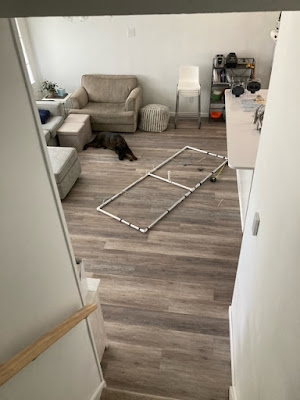
I had both heard, and read about an antenna called a Moxon, that offered decent front to back ratios, was compact, and depending on design very light weight. There are many webpages and videos that detail how to build these antennas but, in the end, I settled on this site. Not for any particular reason other than I had most of the materials needed for this design. I roughly used the dimensions outlined and just trimmed things until I liked what I saw. Below is the antenna in mid-construction. I merely used electrical tape to secure the wires to the PVC, knowing this was just a test and not anything permanent.


Once I got the antenna together and up on a mast it was time to tune it. The antenna was about twelve feet off of the ground and I took some readings with the NanoVNA.


The first reading came up a bit low. Around 47.5Mhz. Much too low for the six-meter band.

After a few snips with the wire cutters, I was happy where the antenna was roughly tuned.  Below 2:1 SWR for about half the six-meter band.

Next it was time to map out the antenna pattern. To do this I set up WSJT-X software to call CQ on FT8 on the six-meter band. I would lower my wattage to its lowest setting and then just walk around the antenna in a circle thirty feet away from it with a signal strength meter on each transmission. So, standing directly in front of the antenna at thirty feet distance I adjusted the field strength meter to 100% during transmission.

Walking 90 degrees on either side of that point read 100%.


The 180 degrees behind the antenna produced 30%. I felt that this was a very good front to back ratio and allowed decent directivity.


Armed with this information I pointed the antenna West and turned up the wattage to 95 watts and started calling CQ. When I visited PSK Reporter to look at a reception report I was amazed at how far my signal got. I really wasn't expecting to see Texas light up. There must have been a band opening or something to the like.


So, I felt this little experiment was a success. Once I get more time, I would like to build a lighter version of this and get it up on my roof with a decent rotor. But for now, I will take the success that I got.


Saturday, January 14, 2023

The Amazing Melting Antenna

 These days you are much more likely to see solar panels on the roof of a house than you are to see a television antenna peaking above its highest point. This of course is due to technological progress and the dominance of cable TV. 


At some point the temptation of a glut of channels seemed to be worth the ever-increasing cost of having a cable come into your home, and force feed you more reality shows and highly opinionized news then any one person could conceivably imagine. At the price a person pays, the compulsion to lock your eyes open and stare at the vast emptiness of quality programming seems to be almost natural if not necessary. 

Noticing this gaping monthly hole in our wallet combined with the bad taste in our mouths from what was actually being offered to us the watch, the wife and I decided to cut the cable and rely solely on streaming services, and OTA (Over the Air) television.

To accomplish the reception of over the air television (yes, it is still being offered), I put up a small antenna pointed at a particularly thick congregation of television antennas seven-teen miles northwest of my location.


This antenna was once available on Amazon and does provide decent service. It happily hung out on my roof for a few years with a variety of other antennas, sensors, and plumbing.


Recently, however I had noticed a distinct drop in signal strength and quality of picture. Something was wrong up there, and I did not know what. Perhaps some of the high winds we get moved the antenna out of alignment. I had to go up and see.

What used to be an easy climb up onto my roof has since become somewhat of a task the older I get. Nonetheless I did hobble up to see what was going on. The first thing I noticed was the antenna was absolutely COVERED in bird shit. Is bird shit conductive? Was it shorting something out? I did not know. So, whatever the reason I had to take the antenna down and clean it up.

Below you can see the antenna after it has been cleaned up a bit. It does still appear a bit rough around the various feed points. In my attempt to clean those up, the plastic holding them secure fell apart in my hand. I suppose the years of it baking in the sun and bathing in bird shit had just deteriorated them. 


Luckily, I have a 3D printer and a mind to use it.  I was able to design and print a reasonable facsimile that worked rather well.


This time I mounted everything in the attic to keep the birds away from the antenna. I pointed things in the right direction, and everything was good. The signals were strong, and the picture was solid. I had all of this completed before the summer heat got too hot to work in the attic.

After about a week I started to notice that channel 2 was not coming in at all. This didn't make sense to me since the signal was nice and strong when I hung the antenna. I popped up into the attic to take a look and this is what I saw. The elements responsible for VHF-Lo band reception (Channel 2) were bent over and sagging as if they were sad. On further inspection when I took the antenna apart, I found out that my printed PLA parts had gone soft and melted a bit.


How was this even possible? The attic should never get that hot. Well apparently, it did because I had found that my attic fan had stopped working. So, I took the antenna apart and put it to the side while I fixed the attic fan.

In the end however I hooked my discone antenna up as a stop gap until I repaired the directional antenna again. Come to find out that the discone antenna works WAY better than the direction one I fixed. So, I just left it in place and have not had issues with it since.


Another lesson learned; I suppose.