Tuesday, April 18, 2023

Home Theater Fan Repair


These days it would seem as if every product were manufactured with an engineered lifespan. I find this particularly true with cheaper electronics. Parts and components of a unit typically fail at what seems suspiciously close to mere weeks after a warrantee period has ended. For some, this equates to the slow sad procession of obsolete electronics to the curb on trash night. To others like me, it lends an opportunity to open a unit up to see if something could be repaired or at least harvested for parts.

Case in point, my father gave me an old surround sound decoder he no longer wanted. I had purchased him a sound bar which better suits his needs and he simply wanted to discard the old decoder. I had asked him if it worked, and he said that it did but that it made a “funny noise”. Not deterred, I took it home and opened it up.

               Once the cover was off, nothing seemed out of the ordinary. Typically, the first thing I look for is any signs of stress or wear on the components. None of the capacitors looked swollen and there were no observable burn marks or loose solder joints. So, at first glance everything seemed ok.

               The next thing I did was hook the speakers up, apply power to the DUT (device under test) and then listen for or smell if anything seemed out of place. No sparks, or smoke erupted when power was applied. Furthermore, nothing seemed to burn or smell different. The speakers had a very slight hiss to them when the volume was turned up, so nothing with them sounded like a “funny noise”.


There was, however, a guttural whirling that emanated from the DUT. On closer inspection it appeared that the fan was struggling to spin. “Ahh this must be the problem!”, I thought. That seemed like a simple enough fix. Maybe even a quick blast of air could remedy things.

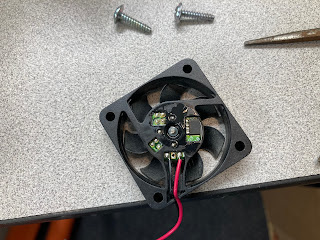
               I popped the fan out of the DUT and gave it a good blast of air. I noted that as per the label the fan ran on 12 volts, so I decided to hook it up to a power supply to ensure that the fan was still in working order. I dialed up the voltage on the power supply and the fan snapped to life with vigor. It ran a little loud, but it moved the air just fine. I was confident that the issue had been resolved and replaced the fan in the DUT.


Upon testing, the fan performed in the same manner I had originally observed. It struggled to spin. This led me to believe that somehow the board was not providing the voltage necessary to turn the fan.

               I disconnected the fan and read the voltage with a multimeter at the connection point. It was a little over 8 volts. “Well, that is not 12 volts so that HAS to be the problem.”, I thought to myself.

               At this point I was a little over my head. Somewhere, I imagined there had to be bad components buried in the complex circuitry of the DUT. I searched with no success to find a schematic. I attempted to look at the traces on the board to get some sense of where to look next. Ultimately, I just started to randomly probe around looking for 12 volts on the board.

               When none of this worked, I decided to enlist the help of fellow club member Chris Prioli, AD2CS. He informed me that he would be happy to take some time and look at my problem.

               More often than not, there is always something going on at the clubhouse every Saturday. Whether it is a Tech Saturday presentation, the satellite station flexing its muscles on the newest satellite deployed or restoring the clubhouse to better than former glory. The activity there is both welcoming and productive. This was the perfect place to meet up with Chris, and to get some use out of the clubhouse’s test bench.

               I met up with Chris early on Saturday morning and after a few moments of discussing Chris’ latest project we moved to the test bench to diagnose my issue. I explained the problem that the DUT was experiencing to him. He then did a quick search for a service manual to no avail.  We also removed the board in question and did a visual examination, nothing seemed out of place.

Next, we hooked the DUT up to the test benches’ isolated AC power supply. This was an interesting piece of test equipment that isolates any circuit powered by it from AC mains. It also had the ability to adjust the voltage so that a user can slowly increase the voltage up to the recommended value. The DUT powered up normally and when turned on via the front panel switch, the fan began to intermittently spin.

               Up to this point the steps taken were nearly identical to what I had performed in my earlier analysis. Chris, however, took a different approach when he checked the voltage being delivered to the fan. Instead of using a multimeter he opted to use the oscilloscope instead. I asked about this and he informed me that the “scope” could give us much more information about the voltage than merely its value. For instance, it can tell us if it is flat or alternating in any form over time. For the DUT it appeared that the voltage was a flat DC value a little more than 8 volts. This led us to believe that the voltage being delivered was probably not the issue since it was constant, with little to no ripple in it.

               Chris had me remove the fan again, and he visually inspected it.  “Look here.”, he said to me while spinning the fan blades with his finger. He continued, “The fan does not spin smoothly, there is some resistance”, while flipping the power switch of his custom battery eliminator. This is a piece of test equipment that Chris had built of his own design. It allows a user to flip through a series of DC test voltages that are common battery voltages. We started low at 1.5 volts and gradually increased. The fan started to intermittently turn at around 8 volts and finally started spinning consistently around 12 volts.

Then it occurred to me that DC fans should ideally start spinning with low voltage and gradually get faster, NOT run intermittently. It seems like an obvious enough thought, but it had indeed eluded me, with my limited experience in troubleshooting. So, my original impression that the fan was the issue was correct and Chris agreed.

Rather than order a new fan, Chris wanted to see if we could restore the operation of the fan under test. He peeled off the label on the back of the fan to expose the electronics and bearing. He then used component cleaner and compressed air to dissolve and blow out any dirt in the moving parts. Finally, we hooked the fan up to a voltage source to get it spinning and we applied oil to the bearing. Now the fan spun smoothly as soon as voltage was applied. We reinstalled the fan and the DUT now had no issues.

There were a couple of different ways that I could have addressed the problem. I could have scraped the unit for parts, or I could have merely ordered a new fan, waited for its arrival and installed it. Either would have worked out for me, but I feel that it would have wasted the opportunity to learn and collaborate with fellow enthusiasts. After all, isn’t that what being in a club is all about?


Sunday, January 15, 2023

The Six Meter Moxon

 For some time now I have been punishing my antenna tuner and radio by attempting to tune a ten-meter hamstick dipole to six meters. At times, I could just barely keep my radio transmitting long enough to squeeze out a few FT8 contacts. There had to be a better way to get on six meters. Sure, I could just buy a few more hamsticks for that band but I'd like to save that money for the purchase of a GOOD multi-band vertical, if at all possible, Plus I have a bunch of wire and building materials just laying around from my years of hoarding such things. So, I thought maybe I could try and build an antenna for six meters.

This is nothing new for me. In the past I have attempted to build a three element Yagi out of discarded tape measures, and even simpler, a dipole I made out of galvanized conduit. I was never able to get the Yagi to work properly and the PVC support for the tape measures sagged comically. I did however get the dipole to work somewhat properly, and I think I even recall making a contact to someone in Delaware., but the whole thing was heavy and unwieldy. I simply lacked the equipment, the knowledge, and the patience to make a decent antenna of moderate size.

Now a days we have great tools like the Nano VNA and PSK Reporter. For me this makes building and testing antennas so much easier. In the past I merely hooked an antenna up to my little MFJ-259 to see that it wouldn't burn out my finals if I transmitted. I really had no way of seeing any other attributes or performance statistics. At least none that I could visualize.

So, I think this time around I am better prepared to come up with a solution to getting onto the Magic Band.

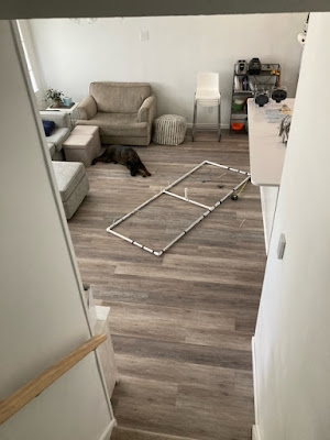
I had both heard, and read about an antenna called a Moxon, that offered decent front to back ratios, was compact, and depending on design very light weight. There are many webpages and videos that detail how to build these antennas but, in the end, I settled on this site. Not for any particular reason other than I had most of the materials needed for this design. I roughly used the dimensions outlined and just trimmed things until I liked what I saw. Below is the antenna in mid-construction. I merely used electrical tape to secure the wires to the PVC, knowing this was just a test and not anything permanent.


Once I got the antenna together and up on a mast it was time to tune it. The antenna was about twelve feet off of the ground and I took some readings with the NanoVNA.


The first reading came up a bit low. Around 47.5Mhz. Much too low for the six-meter band.


After a few snips with the wire cutters, I was happy where the antenna was roughly tuned.  Below 2:1 SWR for about half the six-meter band.

Next it was time to map out the antenna pattern. To do this I set up WSJT-X software to call CQ on FT8 on the six-meter band. I would lower my wattage to its lowest setting and then just walk around the antenna in a circle thirty feet away from it with a signal strength meter on each transmission. So, standing directly in front of the antenna at thirty feet distance I adjusted the field strength meter to 100% during transmission.

Walking 90 degrees on either side of that point read 100%.


The 180 degrees behind the antenna produced 30%. I felt that this was a very good front to back ratio and allowed decent directivity.


Armed with this information I pointed the antenna West and turned up the wattage to 95 watts and started calling CQ. When I visited PSK Reporter to look at a reception report I was amazed at how far my signal got. I really wasn't expecting to see Texas light up. There must have been a band opening or something to the like.


So, I felt this little experiment was a success. Once I get more time, I would like to build a lighter version of this and get it up on my roof with a decent rotor. But for now, I will take the success that I got.


Saturday, January 14, 2023

The Amazing Melting Antenna

 These days you are much more likely to see solar panels on the roof of a house than you are to see a television antenna peaking above its highest point. This of course is due to technological progress and the dominance of cable TV. 


At some point the temptation of a glut of channels seemed to be worth the ever-increasing cost of having a cable come into your home, and force feed you more reality shows and highly opinionized news then any one person could conceivably imagine. At the price a person pays, the compulsion to lock your eyes open and stare at the vast emptiness of quality programming seems to be almost natural if not necessary. 

Noticing this gaping monthly hole in our wallet combined with the bad taste in our mouths from what was actually being offered to us the watch, the wife and I decided to cut the cable and rely solely on streaming services, and OTA (Over the Air) television.

To accomplish the reception of over the air television (yes, it is still being offered), I put up a small antenna pointed at a particularly thick congregation of television antennas seven-teen miles northwest of my location.


This antenna was once available on Amazon and does provide decent service. It happily hung out on my roof for a few years with a variety of other antennas, sensors, and plumbing.


Recently, however I had noticed a distinct drop in signal strength and quality of picture. Something was wrong up there, and I did not know what. Perhaps some of the high winds we get moved the antenna out of alignment. I had to go up and see.

What used to be an easy climb up onto my roof has since become somewhat of a task the older I get. Nonetheless I did hobble up to see what was going on. The first thing I noticed was the antenna was absolutely COVERED in bird shit. Is bird shit conductive? Was it shorting something out? I did not know. So, whatever the reason I had to take the antenna down and clean it up.

Below you can see the antenna after it has been cleaned up a bit. It does still appear a bit rough around the various feed points. In my attempt to clean those up, the plastic holding them secure fell apart in my hand. I suppose the years of it baking in the sun and bathing in bird shit had just deteriorated them. 


Luckily, I have a 3D printer and a mind to use it.  I was able to design and print a reasonable facsimile that worked rather well.


This time I mounted everything in the attic to keep the birds away from the antenna. I pointed things in the right direction, and everything was good. The signals were strong, and the picture was solid. I had all of this completed before the summer heat got too hot to work in the attic.

After about a week I started to notice that channel 2 was not coming in at all. This didn't make sense to me since the signal was nice and strong when I hung the antenna. I popped up into the attic to take a look and this is what I saw. The elements responsible for VHF-Lo band reception (Channel 2) were bent over and sagging as if they were sad. On further inspection when I took the antenna apart, I found out that my printed PLA parts had gone soft and melted a bit.


How was this even possible? The attic should never get that hot. Well apparently, it did because I had found that my attic fan had stopped working. So, I took the antenna apart and put it to the side while I fixed the attic fan.

In the end however I hooked my discone antenna up as a stop gap until I repaired the directional antenna again. Come to find out that the discone antenna works WAY better than the direction one I fixed. So, I just left it in place and have not had issues with it since.


Another lesson learned; I suppose.